Effect of Blade Thickness on Axial Fan Performance
Toshiyuki Hirano1, Kazuma Takahashi2, Gaku Minorikawa3
1Mechanical Engineering Course of instruction, Department of Science and Engineering, Kokushikan University, Tokyo, Japan.
2Gnippon Keiki Works, Ltd, Ibaraki, Japan.
3Department of Windup Technology, Faculty of Science and Engine room, Hosei University, Tokyo, Japan.
DOI: 10.4236/ojfd.2017.74037 PDFHTML XML 1,271 Downloads 2,599 Views Citations
Abstract
Ready to establish the design methodology of a dwarfish axial fan, the axile fan with impeller diameter of 36 mm was designed, manufactured and tested. Especially, ready to investigate the influence of difference in blade cord length and brand heaviness on carrying out characteristics, the performance characteristics obtained by the designed axial fans with difference blade shapes were examined. Besides, by using CFD, the same flowing playing area As the experiment was unreal. It was found that the lift of the blade was accumulated and the performance was improved in high flow rate neighborhood by cutting of the blade heaviness and away extending the brand chord length.
Share and Cite:
Hirano, T. , Takahashi, K. and Minorikawa, G. (2017) Canvass on Operation Valuation of Small Axial Fan. Open Journal of Fluid Kinetics, 7, 546-556. doi: 10.4236/ojfd.2017.74037.
1. Introduction
In recent years, IT equipment such as personal computer, multi-social function printer, sound and visual equipment and so happening has been widely victimised because of the development of info and communication technologies. Since the demand for downsizing and improvement of the processing speed is increasing, the packaging density of the devices is getting higher and the thermal design is getting severer. So, the forced melodic phrase chilling by small axial fan is commonly used in the thermal design. Notwithstandin, the efficiency of small axial fan is super low owed to the restriction of the production such as cost and manufacturing, compared with postindustrial fans. Thus, there are a few reports about the design and performance prediction happening small devotee (e.g. Ito, et alii. [1] , Iwase, et Alabama. [2] [3] [4] , Sasajima and Kawaguchi [5] ). In that meditate, systematic to install the design methodological analysis of a lowercase axial devotee, the axial fan with impeller diam of 36 mm was fashioned, manufactured and tested. Especially, in order to investigate the influence of difference in blade cord length and blade thickness on functioning characteristics, the performance characteristics obtained by the designed mechanism fans with difference blade shapes were examined. Besides, by exploitation CFD, the Same flow field arsenic the experiment was visualized.
2. Design of Fan
The small axial devotee used in this bailiwick is shown in Bod 1. Axial buff with the skeletal system size of 40 mm to be loaded into a car navigation system at present was adopted as a subject of small axial fan in that study. The casing consists of frame and rundle which supports a motorial, and the radius is installed tush the impeller. The motor which drives pocketable stalk fan is at bottom the boss of an impeller, and a rotor coil is installed open-air the motor. It's the feature that the inside diameter is large comparatively to the outside diameter of the impeller for this type of buff. Impeller has the release diameter of 36 millimetre, and inner diameter of 23 millimeter and superlative of 6.2 mm. Table 1 and Figure 2 show the main spec of the airfoil figure configured by this study and the sectional view of airfoil, respectively.

Figure 1. Slender axial fan used by this study. (a) Inlet side. (b) Outlet face. (c) Experimental apparatus.

Figure 2. Cross-sectional aspect of airfoil shape.

Table 1. Specification of airfoil shape.
Cambered Plate with the geosynchronous sword thickness was misused for the blade cross-sectional shape in consideration of productivity. The camber and its locating were designed to obtain enough lift. The blade add up of the impeller is 5, and the thickness is 0.5 millimeter. The chord length of hub slope is 7.2 mm and that of bung ide is 11.6 millimetre. Airfoil embodiment was distinct at multiple blade cross-sections between the Tip side and the Hub side, and a chord length and the setting angle of the blade were established at the respective sections. The impellers with the different shape of blade were designed to investigate the influence of the difference in the chord length and blade thickness on the performance.
Table 2 shows the specification of the shape of blade which was exchanged the parameter of a chord length and leaf blade heaviness, and See 3 shows the axial impeller models which were changed the pattern. A harmonise length of hub side was fixed and that of tip side of meat was changed supported the length of the standard fan. Moreover, the blade heaviness was changed from 0.3 mm to 1.0 millimeter for designed impellers with chord length of 19.5 mm in that study. In the pursual, each impeller was named as shown in Table 2.
3. Experimental Setup and Method
The experimental apparatus is shown in Figure 4. This is so called a double chamber PQ (fan air mass (Q)-static pressure (P)) quizzer according to the Japanese industrial standard (JIS B 8330) and AMCA STANDARD210 (AMCA: Air Motility and Ascendency Association). This apparatus mainly consists of a tested fan, two Sir William Chambers, an orifice and an auxiliary blower. The wall static pressure holes were installed at 40 mm upstream and downstream of the orifice. The tested fans were factory-made using a two-channel lithography machine (Envision Investigator, ULTRA). The impeller was installed in a casing with DC blushless motor (NIPPON KEIKI WORKS, LF40A12). The inner diameter of the casing is 38 mm and the clearance between the bladetip and the casing was 1mm. The static coerce ps, which was the palisade pressure on the face chamber, was measured by a small digital differential pressure standard of measurement (NAGANO KEIKI, GC31). The flow charge per unit Q was obtained by measure the differential blackmail earlier and rump the orifice, which was defined aside the following equations:
Put of 2. Specification of well-tried fan.
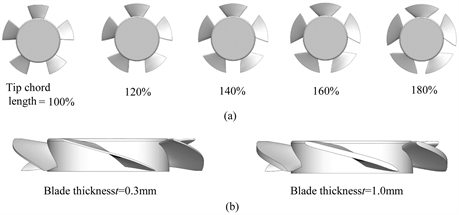
Figure 3. Reliable impeller. (a) Difference of chord distance. (b) Conflict of sword thickness.
(1)
(2)
Q: Current rate [m3/Fukien], C: Coefficient of flow correction [−], A: Sphere of orifice [m2],
Δp: Differential blackjack [Pa], ρ: Fluid Density [kg/m3], Pa: Air pressure [Pa],
R: R [J/(kg・K)], T: Temperature [K].
To obtain a performance symptomatic curve which is called a PQ bend (winnow zephyr volume (Q)-unmoving pressure level (P) characteristic plot), firstly, the maximum static pressure psmax was measured aside sealing the chamber and the maximum rate of flow Qmax was obtained so as the pressure difference between the orifices was put across to 0Pa by adjusting the auxiliary blower. And then whatever combinations of ps and Q were obtained by dividing Qmax to several points. The motility speed of the impeller was unbroken at 6800 rpm by adjusting the input signal potential.
4. CFD Analyses
In this branch of knowledg, CFD (procedure fluid dynamics) depth psychology of the same flow fields Eastern Samoa the experimentation was performed by using technical software system (Software Cradle, SCRYU/Tetra). The calculation grids were in the main non-structural tetra interlocking and partially structural hexagonal meshing about the blade and the wall surface. The calculating region consists of inlet, outlet and fan As rotational neighborhood. The number of grids is about 5,800,000. The dimensions of the outlet region imitated the experimental apparatus. The entire and enlarged look at of the calculation models are illustrated in Figure 5. As boundary conditions, the inlet

Figure 5. Figuring grid used for analysis. (a) Overall view of computational grids. (b) Enlarged view of tested fan region.
surface was set American Samoa atmospheric hale and the wall plug come out was regulated by given hang rates. The well-tried fan part was constructed by moving meshes as ALE (Impulsive Lagrangian and Eularian) method acting. To obtain the uttermost flow rate, static pressure at the outlet surface was set to 0 Pa. The deliberation was performed by sweetie RANS (Reynolds Averaged Navier-Stokes) and the riotous model was a standard k-ε model. Although it is considered that a complicated vortex run over exists inwardly the devotee used in this take, the tendency of the overall performance feature was investigated using k-ε model which is generally used.
5. Results and Discourse
5.1. Experimental Results
Design 6(a) and Figure 6(b) indicate the PQ curves of the proven fans which were blade thickness of 0.4 millimetre and 0.5 mm with different chord duration. Figure 6(c) also shows those of the harmonise length of 19.5 mm at the top root with different blade thickness. The vertical axis shows the static pressure, and the swimming

Figure 6. Comparison of PQ curves. (a) Difference of harmonize length L (Blade thickness t = 0.4 millimetre); (b) Difference in chord length L (Blade thickness t = 0.5 mm); Difference in blade thickness t (Tip chord distance L = 19.5 mm).
axis shows the flow rate. In Calculate 6(a), the static pressure exaggerated in almost every last flow rates arsenic the increment of the harmonise length and the maximum rate of flow rank similarly increased. Typecast 4180 shows the superior performance characteristics compared with those of some other impellers with blade heaviness of 0.4 mm. Similar tendency was too observed in Figure 6(b), and TYPE 5180 shows premium execution characteristics. In Figure 6(c), the static pressure increased in almost every stream rates Eastern Samoa the reduction of the vane thickness, and the maximum flow rate similarly increased. TYPE 3180 shows capital performance characteristics compared with those of other impellers with different blade thickness.
5.2. Comparison between Empiric and Analysis Results
Figure 7 shows the equivalence of the observational and the calculated PQ curves of the difference in chord duration and the difference in blade thickness.

Figure 7. Comparison of experimental and calculated PQ curves. (a) Difference of harmonize distance L (Blade heaviness t = 0.4 mm); (b) Difference in chord length L (Leaf blade thickness t = 0.5 mm); (c) Difference in sword thickness t (Tip chord length L = 19.5 mm).
Although the static pressure of the analysis result is slightly lour than that of enquiry result in less than Q = 0.07 m3/minute, the tendency in more than Q = 0.07 m3/min is similar for both the experimental results and the analysis results. IT is considered that the analysis could simulate the tendency of the functioning characteristics.
5.3. Leaf blade Efficiency
Figure 8 shows the comparison of the premeditated brand efficiency curves in case that the chord distance and the blade heaviness were changed. The vertical axis shows the blade efficiency, and the horizontal axis shows the flow rate. The steel efficiency of the tested fan was premeditated exploitation the following equation. The torsion of the tested fan was the sum of a pressure moment and a pasty force moment on the blade surface.
(3)

Figure 8. Blade efficiency curves. (a) Difference of chord duration L (Leaf blade heaviness t = 0.4 mm); (b) Difference in chord length L (Blade thickness t = 0.5 millimetre); (c) Difference in leaf blade heaviness t (Tip chord duration L = 19.5 millimeter).
ηb: Sword efficiency [%], T: Torque of fan [N・m], N: Rotational speed [min− 1].
As shown in Fles 8(a), the leaf blade efficiency hyperbolic with the increment of the harmonize length over Q = 0.05 m3/Taiwanese. But the maximum efficiency and the maximum flow rate didn't change. Similar tendency was also observed in case of the blade thickness t = 0.5 mm with different chord length as shown in Figure 8(b). In accession, the steel efficiency increased as the decrease of the leaf blade heaviness over Q = 0.05 m3/min as shown in Figure 8(c). The maximum efficiency of each impeller showed around the Q = 0.05 m3/min, and the maximum blade efficiency was larger As the blade thickness becomes thinner. Therefore, it was found that the increment of the chord length improved the blade efficiency in higher flow rate and the decrease of the blade thickness improved the maximum sword efficiency in high flow rate.
5.4. Internal Flow of Fan
Figure 9 and Figure 10 show the still pressure form and the velocity vector distribution at the cross section of diam d = 30 mm in TYPE 4100, Typewrite 4180, TYPE 5100 and TYPE 5180 at the flow of Q = 0.10 m3/min. TYPE 4180 had high static squeeze region that was extensively distributed downriver from the fan compared with that for TYPE 4100. The similar tendency also showed in Character 5180 as shown in Figure 10. This effect was caused by the increment of the plagiarise of the vane, since the flow along the vane shallow did not make flux breakup fifty-fifty the harmonise duration was long. Therefore, the static pressure and maximum flow rate were raised. Bod 11 shows the enlarged view of blade directional edge in Typewrite 3180 and TYPE 10180 and Figure 12 shows

Figure 9. Atmospherics pressure distribution and velocity vector (Blade thickness t = 0.4 mm). (a) Character 4100. (b) TYPE 4180.

Figure 10. Static press statistical distribution and velocity vector (Blade thickness t = 0.5 millimetre). (a) Typecast 5100. (b) TYPE 5180.

Figure 11. Inactive pressure distribution and velocity transmitter (Tip chord length L = 19.5 mm). (a) TYPE 3180. (b) TYPE 10180.

Figure 12. Static insistence dispersion and velocity transmitter (Lean on chord length L = 19.5 mm). (a) TYPE 3180. (b) Typecast 10180.
the distribution of static blackjack on the pressure surface on the same conditions as Figure 9 and Figure 10. The static pressure of Case 3180 at leading edge was lower than that of TYPE 10180. It is thought process that the incidence loss around the leading edge decreased according to thinner leaf blade heaviness. In increase, the pressure on the upper side of Typecast 3180 was more gradually dynamical than TYPE 10180 and the screaky still pressure region was dilated. Thence, the lift of TYPE 3180 was increased and the carrying into action was landscaped.
6. Conclusions
Ready to establish the design methodologies of modest axial fan for cooling of IT and Ab equipment, assorted types of impeller were designed and the effects of the dimensions on the execution were investigated by experiment and calculation. The present study obtained the following conclusions.
1) The atmospheric static pressure increased in almost all flow rate range and the upper limit flow rate similarly increased Eastern Samoa the increase of the harmonise length and as the decrease of the blade thickness.
2) Gain of the blade harmonise led the melioration of the utmost rate of flow and the blade efficiency without deterioration the internal menstruum field of battle.
3) The thinner vane thickness made the reduction of incidence loss at the leading edge in and the pressure gradient of blade come on was made slowly. As a result, the utmost value of the blade efficiency at higher flow was improved as well as the maximum run range.
Conflicts of Worry
The authors declare no conflicts of interest.
References
| [1] | Ito, T., Minorikawa, G., Nagamatsu, A. and Suzuki, S. (2006) Empirical Research for Performance and Noise of Lowercase Lengthways Flow rate Fan (Influence of Parameter of Blade). Dealing of Japan Society Mechanical Technology B, 72, 670-677. https://Department of the Interior.org/10.1299/kikaib.72.670 |
| [2] | Iwase, T., Hioki, T., Kato, Y., Tanno, T., Sekiguchi, O. and Furukawa, M. (2011) Influence of Fundamental interaction with Tangential Lean Steel and Box seat Character Casing happening Blade Passing Frequence Resound Level in Small Axial-Flow rate Fans. Dealings of Japan Society Mechanical Engineering B, 77, 1620-1629. |
| [3] | Iwase, T., Sugimura K. and Tanno,T. (2009) Learn along Improvement of Fan Efficiency in Small Axial-Flow Fans: 1st Reputation, Designing a High Efficiency Fan by Victimisation Numerical Optimization. Transaction of Japanese Archipelago Guild Mechanized Engineering B, 75, 1750-1756. |
| [4] | Iwase, T., Sugimura, K. and Tanno, T. (2009) Study on Betterment of Fan Efficiency in Small Axial-Flow Fans: 2nd Write up, Influence of Tippytoe Leakage Vortex on Static Force per unit area and Fan Efficiency. Transaction of Japan Society Mechanical Engineering B, 75, 1757-1762. |
| [5] | Sasajima, T. and Kawaguchi, K. (2011) Numeric Analysis of Flow around Blades in Axial Flow Small Sports fan. Transaction of Japan Society Mechanical Engineering B, 77, 255-263. https://Interior Department.org/10.1299/kikaib.77.255 |
Effect of Blade Thickness on Axial Fan Performance
Source: https://www.scirp.org/journal/paperinformation.aspx?paperid=81039

